FreeTrack Forum
FreeTrack Forum > FreeTrack : English Forum > Support : Tracking System > Your point model constructions
| biton161 | #121 16/01/2010 - 20h40 |
|
Class : Apprenti Off line |
Here are some pics of my model - SFH485 (not P) based on 5V USB power with a resistor in series (simplest setup I could find).
 The joints are made of old PC microphone stands with the wires going through to a little wooden compartments I fabricated from various wooden parts. Within it the wires are soldered together, to the resistor which is detachable so I can replace to enhance/reduce intensity (the 11ohm resistor provides about 60ma which was sufficient for tracking with a Wiimote), and to the USB wire. Here is a pic of the final model after finishing. I used a the clip torn off a LED lamp to provide adjustment capability (in the pic you may be able to see the joint) :  Here is a close-up view of the joint (sorry for the focus) :  Here is a pic with the clip assembled :  I use the Wiimote as an IR cam. I assembled this fixture from cardboard so I may rest the Wiimote on top of the monitor :  And here it is with the Wiimote in it :  |
| sidewinder | #122 19/01/2010 - 20h06 |
|
Class : Apprenti Off line |
Hello there!
I made some experiments with techsolo webcams and SFH485 diodes, but the result wasn't satisfying. You are not able to remove the IR filter of any techsolo webcam. So the construction only works in low light conditions and the viewing angle is very narrow. (sorry - no pictures were taken) So i got the idea to grab a spare camera from our optitrack motion capture system.  It is an Optitrack V100 USB IR camera wich produces a grayscale image with high FPS output. It is equiped with 30 IR LEDs - they lighten up every reflektive material even in the distance. I attached the cam directly to my computer and placed it on my screen.  I also placed three spare markers (comes with the mocap system) on one of the mocap-suites hats, like shown in the freetrack software.  Because the hat material is velcro you can attach the markers instantly. The result is amazing!!! Freetrack shows 100 fps and the tracking is very accurate. I can jump around and bend the head over, freetrack do not loose track even in bright daylight. This is the instant freetrack system. The whole setup incl. freetrack installation took me less then 10 min! Because all materials used are spare parts, I could borrow them to play Flight Simulator X :-) Greetings sidewinder |
| aviatorsneah | #123 11/02/2010 - 13h30 |
|
Class : Apprenti Off line |
My 3 point hat:
-3 IR high output LEDs (filed down flat) -33 ohm resistor -4 AAA battery pack with on/off switch (all bought from radioshack) -wiring strung through lining of hat, heatshrink LED mounts wired to hat -Microsoft VX1000 webcam -Works GREAT in IL2! Thanks Freetrack! 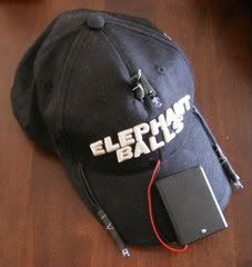
Edited by aviatorsneah on 11/02/2010 at 13h32.
|
| kirock7 | #124 13/02/2010 - 21h09 |
|
Class : Apprenti Off line |
Well, I guess it's time to throw my hat into the ring (so to speak :-))
This is my first (and so far only) build; a three-point IR LED hat using the recommended SFH485P LEDs, three 27 ohm resistors, mini-switch and power supply consisting of two AA batteries. Using FreeTrack 2.2 and a Microsoft VX-1000 web cam mounted on top of my monitor. IR filter removed and piece of floppy disk applied to the front of the camera for light filtration. This rig works really really well. You'll notice that my old digital Canon can see a little of the IR in these shots (the hat is turned on) so they have a slight glow. In the setup screen for FT these things are bright enough to allow me to filter out almost all backlight (sun, lamps or otherwise). I get a constant 30FPS and 0 to 2 on the jitter meter. The components are all stuck up under the lining of the hat so they are impossible to feel and the batteries (with velcroed battery case) is completely unnoticeable after the hat is on my head. Please excuse the dirty underside of the brim. This had been my favorite hat for a very long time and got a lot of use and abuse before becoming my IR tracking model. :-) With the components I have left over I'll be building another model soon using a brand new and therefore much cleaner hat. LOL!     UPDATED: Here's a video recorded while wearing my IR head tracking cap: http://www.youtube.com/watch?v=Sf6c_j4kHH4 UPDATED AGAIN: Thought I'd toss in a few more videos in case you're an addict for this game. http://www.youtube.com/watch?v=Sf6c_j4kHH4 http://www.youtube.com/watch?v=-DgurKU0OOk
Edited by kirock7 on 15/02/2010 at 00h32.
|
| zoog | #125 23/02/2010 - 21h05 |
|
Class : Apprenti Off line |
This was actually my prototype, but it works perfect so now I'm too lazy to make it look better (shorter wires, better construction etc.).
    |
| erichhart | #126 17/03/2010 - 01h29 |
|
Class : Apprenti Off line |
What is yours running off AA or 4 AAA
|
| zoog | #127 17/03/2010 - 14h42 |
|
Class : Apprenti Off line |
2 x AA batteries |
| buccaneer | #128 24/03/2010 - 13h34 |
|
Class : Apprenti Off line |
Found offcut of a plastic window sill laying around (can happen when you have renovation in progress
 ) Top surface appeared to be quite dense and thick (2.5 mm). Some manipulations with jig saw and i have the clip frame. ) Top surface appeared to be quite dense and thick (2.5 mm). Some manipulations with jig saw and i have the clip frame.   Three IR LEDs (HIRB-43D-C) underwent some filing  There were several tries how to mount LEDs on the frame. Final one was to use plastic dowels as LED holders and to tie them to the frame with plastic cable ties. The rest was rather straightforward. Here is the final product   Took several frontal and side-view pictures of me wearing the clip and holding a ruler (for measurements reference). After a bit of manipulating with images in photoshop i had final clip dimensions and pivot point position. 
Edited by buccaneer on 24/03/2010 at 13h41.
|
| WarpSpider74 | #129 25/03/2010 - 10h47 |
|
Class : Apprenti Off line |
G'day all!
Finally getting around to posting my build. I used benmeijer's excellent post as inspiration.  Used SFH485P LED's, bloody hard to find in Australia. Ended up finding them at Farnell's if anyone else is after some. I first made a 3-point clip model that ran off batteries and had inferior narrow angle LED's, but I found it too heavy when attached to my headphones. So the pictured version is much more streamlined and runs off USB power.   Clip bent up from coathanger wire, black heatshrink to spiff it up a little bit (also to insulate but appearance is more important here lol)  Cable-tied onto right side of headphones. Would personally prefer left side, but the mic is in the way. Cable routed over to left side, cable-ties on the sides but this proved uncomfortable on the headband, so the cable is cemented across the top of the headband. Much better.  The complete package. The cable is spot-cemented to the headphone cable to keep it out of the way, used the cable from an old Nokia phone charger which is light, very flexible, and doesn't look out of place (also, it was exactly the right length!!) The box is a 90 cent 2xAA battery holder I had from another project. Stripped the guts out of it and added an indicator LED, the box already had an on/off switch. Resistors and PTC fuse are in there, keeps them out of the way and lets me turn the LED's off when I'm not using FreeTrack.  Why anyone persists with webcams when you can buy second hand Wiimotes for around $10 has me stuffed. Wiimote all the way baby! Monitor mounting bracket bent up out of coathanger wire and coated in black heatshrink to prevent scratching. All set up, works a treat. I mainly fly in Condor, X-Plane and LOMAC, and the rig works well in all three. Also works in EVE Online, though I don't usually use it. That's Condor on the monitor btw. Happy Tracking! |
| benmeijer | #130 26/03/2010 - 10h30 |
|
Class : Habitué Off line |
Nice clean build, especially the precise bent of a coathanger, so it's simple if you're want the exact dimensions of the real one.
I also like your WiiMote solution for mounting it on your monitor. Could you post a larger image of that, without the WiiMote. |
| WarpSpider74 | #131 26/03/2010 - 14h13 |
|
Class : Apprenti Off line |
Thanks mate!! The coathanger wire model took literally 5 minutes to bend up once I'd sketched it up. The measurements used were the default dimensions listed in the 3 point clip model tab in FreeTrack. Here's my original build, which worked but sucked. LED's were too narrow angle even when filed down, battery weight was uncomfortable on my lightweight headset. I don't wear big chunky headphones like a lot of guys on here seem to... I actually place some stock in hearing what's going on around me (kids for example  ) Also it looked plain silly having all that guff hanging off my headset. The new one looks much more the part. ) Also it looked plain silly having all that guff hanging off my headset. The new one looks much more the part.
Ask and you shall receive...  Just to show how the bracket sits on the monitor. The uncoated support beneath the wiimote on the right can be bent to different angles to induce an appropriate angle of tilt.   The coated part to the right grips the front of the monitor bezel, the uncoated leg rests against the back (I would have coated that bit too, but I got sick of stretching heatshrink over all those corners  ) The rest is pretty self explanatory, the coated tail to the left wraps around the back and sides and rests in the groove around the wiimote. That was unintentional, but it works so well in gripping the wiimote and keeping it in place I may as well claim it as a design feature ) The rest is pretty self explanatory, the coated tail to the left wraps around the back and sides and rests in the groove around the wiimote. That was unintentional, but it works so well in gripping the wiimote and keeping it in place I may as well claim it as a design feature  I've also since added a USB charged wiimote battery, so there's a cable that hangs down the back of the rear leg. I've also since added a USB charged wiimote battery, so there's a cable that hangs down the back of the rear leg.Hope this is of some use to others, I borrowed enough ideas off the rest of you! |
| MrVrielink | #132 28/03/2010 - 13h05 |
|
Class : Apprenti Off line |
.
Edited by MrVrielink on 03/08/2010 at 19h43.
|
| mimix | #133 05/04/2010 - 21h13 |
|
Class : Apprenti Off line |
hello everybody !
my fist contribution: wiimote stand for lcd:  made with FIMO modeling paste.
Edited by mimix on 05/04/2010 at 21h14.
|
| maxmala | #134 06/04/2010 - 22h06 |
|
Class : Apprenti Off line |
Hello ! I'm new member.
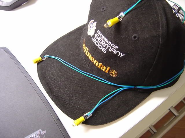
Excuse me for my poor English (I'm Italian). I made my point system for FreeTrack with a cap, three led USB lamps and one USB hub buyed in a Chinese shop. Look that:    
Edited by maxmala on 07/04/2010 at 19h19.
|
| Doctored | #135 18/05/2010 - 01h09 |
|
Class : Apprenti Off line |
I have de idea of use some "wire clamp" on a 3 Leds Caps...and this worked very fine !!
 See the whole assembly at: www.youtube.com/watch?v=BG8fSWala0c  Thanks everybody Thanks everybody |
FreeTrack Forum > FreeTrack : English Forum > Support : Tracking System > Your point model constructions
> Stats
1 user(s) connected during the last 10 minutes (0 member(s) and 1 guest(s)).
Powered by Connectix Boards 0.8.4 © 2005-2024 (8 queries, 0.023 sec)